Test Chamber
Overview
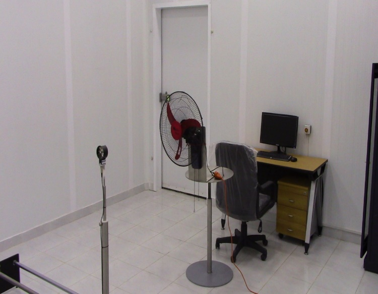
This test laboratory is a comprehensive single enthalpy difference chamber. The laboratory contains a set of air volume measuring devices. The test chamber uses 100mm thick rigid polyurethane board and 0.6mm thick color steel plates on both sides for thermal insulation, which has good thermal insulation effect.
This test room contains an external air conditioning system, which is used to adjust the air environment inside the test room. The indoor air is cooled, humidified, and heated to make the temperature and humidity in the test room meet the requirements of the test conditions.
This test system is mainly controlled by computer. The operator is outside the test room, and the personnel will not affect the wind field. The test of the equipment is completed automatically, and the test data is recorded, saved, and the air flow report and energy efficiency rating are automatically generated. This system has advantages of good repeatability, high efficiency, convenient data storage and so on.
Standards:
IEC 60879-2019 “Comfort fans and regulators for household and similar purpose- Methods for Measuring Performance “
Types of UUT :
- Table fan 200 ~ 450mm;
- Floor fan 300 ~ 600mm;
- Column fan
Test Contents:
- Wind speed: table fan, floor fan, column fan
- Air volume: table fan, floor fan, column fan
- Rotation speed: table fan, floor fan, column fan
- Speed ratio: table fan, floor fan, column fan
- Input power: table fan, floor fan, column fan
- Energy efficiency value: table fan, floor fan, column fan
Laboratory Measurement Instrument Indicators:
| No.: | Name | Content | Range | Measurement uncertainty |
| 1 | Temperature sensor | Dry bulb temperature | 0~50℃ | ±0.1℃ |
| 1 | humidity sensor | Relative humidity | 30%~80%RH | ±3%RH |
| 1 | Digital Power Meter | Input electrical parameters | / | ±0.5% |
| 1 | Anemometer | Wind speed | 0.15~5m/s | ±0.2m/s |
Laboratory Room Structure:
| External dimensions | 4700(W)×5700(D)×3100(H) |
| Inner dimensions | 4500(W)×5500(D)×3000(H) |
| Laboratory maintenance structure | 100mm Rigid polyurethane foam insulation |
Experimental Measuring Device:
|
Device |
Type |
Specifications |
|
|
Laboratory |
Anemometer guide |
Stepper motor control |
Brand Beta-Electronics, with a maximum |
|
Table fan guide |
Stepper motor control |
Brand Beta-Electronics |
|
|
Sample holder |
Height adjusted by screw |
Brand Beta-Electronics |
Main Technical Parameters:
- Distance between anemometer slide and sample stage: 1200-2000mm (automatic adjustment).
- Left and right moving distance of anemometer slide: 20-2600mm (automatic adjustment).
- Vertical height of the anemometer bracket: 1200mm, 1500mm.
- Measuring range: 0.40 ~ 30.00m / s
- Measurement accuracy: ± 1% of reading + 1% of range.
- Measurement accuracy: ± 1% of reading + 1% of range.
- Wind speed sensitivity: better than 0.15m / s.
- Temperature probe: range 0 ~ + 50 ℃; accuracy ± 0.5 ℃
- Driving mode: domestic servo motor + guide shaft.
- Control method: computer control.
- Collect data: power value and wind speed value.
- Data processing: Automatic calculation of average wind speed, air volume, energy efficiency Value, and energy efficiency rating.
- Data storage and reference function.
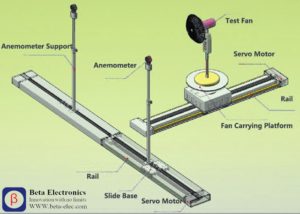
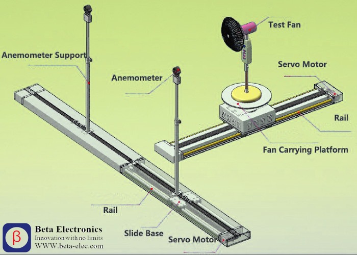
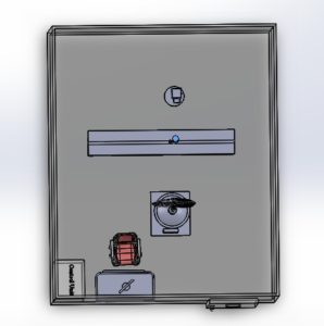
Measurement device layout:
- The equipment is mainly composed of two parts, the air volume testing mechanical part and the computer control system.
- The equipment are installed in a 4500(W)×5500(D)×3000(H) test room.
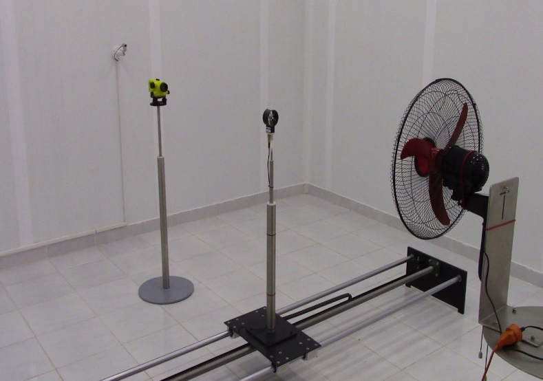
- The air volume test organization is as shown above.
- The sample platform can be manually raised and lowered to adjust the height of the fan center.
- The anemometer base can be moved back and forth and left and right along the XY axis.
- The anemometer base can be moved back and forth and left and right along the XY axis.
- The horizontal position of the anemometer and the fan sample can be adjusted by moving forward and backward.
- Its position is three times the diameter of the fan blade.
- It is driven by a stepper motor.
- When the fan blade diameter is set, it automatically moves to the corresponding position.
- Left and right movement also is driven by stepper motor, the initial position is at the middle zero position, during the automatic test, the computer controls the stepper motor to move the left anemometer to the left 20mm to collect a wind speed value, while the right anemometer collects a wind speed value on the right 20mm position, to complete the wind speed test of a wind ring.
- Then enter another wind ring (ie left 60mm, right 60mm) to measure the wind speed value, the radius difference of each wind ring is 40mm, until the measured wind speed value is less than 24m /min.